|
 INTRODUCTION INTRODUCTION
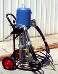
The TSR Grout Pump is a precision machine and must be cared
for as such. Safe, accurate and dependable performance requires
reasonable care and maintenance both before and after operation.
Every pump owner and his operators should thoroughly understand
the information provided with the pump.
PREPARATION
The TSR pump will handle any chemical grout system but it has been
optimized for urethane grouting resins. Most urethane resins are
sensitive to moisture or are activated by moisture, so considerable
care is needed to avoid letting moisture or water into the resin
areas of the grout plant. Before any urethane is introduced to the
pump, the resin side must be flushed with ST-590 or with a solvent
to remove all moisture. Both sides of the pump may require flushing
if the second component is also a resin.
The
first flush is accomplished with ST-590 Kleen-Flush or with a solvent
such as acetone. This may optionally be followed by a 50/50 blend
of Acetone and DiOctyl Phthalate (DOP.). All flushing materials
are introduced through the resin intake assembly. Additional information
and useful hints on techniques may be found in the technical data
sheets for ST-590 and ST-522.
PUMPING
FLAMMABLE MATERIALS
Whenever flammable materials are pumped, such as during cleanup,
connect a ground wire to the pump air motor. Loosen the grounding
lug locknut and washer. Then attach one end of the ground wire (12
gauge minimum) and tighten the locknut securely. Connect the other
end of the ground wire to a good ground point such as a steel building
column or a copper water pipe. Always check your local electrical
code for full compliance with applicable regulations.
The
TSR pump can develop high fluid pressures. Eye protection should
be worn when this unit is in use or energized. The pump is considered
energized until all the cylinder pressure gauges read zero, the
system air is disconnected, and the grout shut off valves at the
downstream end have been opened to relieve pressures.
All
fittings and hoses are rated to loads in excess of the pump capacity.
However, field conditions as well as movement of equipment from
site to site may change the condition of any part. Prior to use,
do a visual inspection of all fittings, hoses and valves at lower
air operating pressures, checking for leakage.
START-UP
Attach a compressed air supply line or compressor to the grout plant
intake located on the front of the pump motor just before the air
pressure regulator. The regulator needle valve should be opened
fully to reduce the air pressure directed toward the pump motor.
To engage the pump motor, shift the valve lever located immediately
above the regulator a 1/4 turn upwards. This will open the double
acting pressure relief ball valve to direct the air flow toward
the pump motor. The pump motor will activate the three pistons in
the assembly.
All
pistons are equipped with recirculating lines to bypass the “A”
and “B” components. The intake lines all enter the lower
section of each piston. The material is drawn from the source by
the stroking of the pistons with a ball check located at the lower
end of each piston. These check valves provide for a positive displacement
of each stroke of the cylinders. The material then exits the top
end of the pistons and enters through flexible high pressure hoses
into a manifold assembly.
The
manifold receives the materials through the intake port and discharges
by opening the valves to the exit port with the bypass ball valve
in the off position. Each manifold usually has two valves and controls
the material intake from each piston pump and the output to the
injection hose. The valves also control the bypass and allow the
material to re circulate into the source container or other storage
vessel.
The manifold is equipped with pressure relief valves to relieve
excess pressure. The materials are pumped through lines coupled
to the manifolds and the flow is directed towards the mixing head
F Assembly. Each F Assembly is equipped with check valves to provide
positive shut off of flow from one material line to the other.
The
“F Assembly” has two ball valves to provide the grouting
technician full control at the mix head.
MIX
RATIO
Each TSR pump can dispense a twin-stream grout at a mix ratio
of 1:1 and another preset ratio selected when the pump is built.
The operator can select which of these ratios he wishes to use but
cannot use any other without replacing the pump cylinders.
At
the beginning of operations and periodically during use, the grouting
technician should check the ratio output of the materials using
a volumetric measuring device to determine exact volume of material
dispensed with each stroke of the pump. Calibration is very simple
and can be done in a few minutes by the operator or inspector. The
grout lines should be disconnected just before the “F Assembly”
when calibrating the material volumes.
When
the discharge lines are off, the bypass or recirculating cylinders
should not be run dry. When the pump operates, fluid should be flowing
in either one or the other.
Should the operator wish to use only one piston directing one material
as a single component, the other cylinders can be positioned in
a recirculating or bypass mode to recirculate the lines.
OPTIONAL FLUSHING ASSEMBLY
The optional flushing assembly (if installed) is conveniently
mounted on the frame next to the pump motor and includes a pressure
pot capable of holding approximately 10 liters of solvent. The assembly
is air activated and has valves to control the air input and materials
output to the pump.
When
flushing is required, hook on the quick couplers to whichever line
requires flushing and pressurize the pot to direct the solvent through
the necessary line.
Caution
should be observed with handling and activating the solvent flushing
system. Safety glasses and complete safety regulations typically
applicable to handling of solvents should be observed. Consult your
MSDS and the product technical data sheet on the safe handling procedures
required for the specific solvents used for the flushing system.
Return
to Grout Pumps
Return
to Top
STATEMENT
Strata Tech believes that the information herein is an accurate
description of the general properties and characteristics of the
product(s), but the user is responsible for obtaining current information
because the body of knowledge on these subjects is constantly enlarged.
Information herein is subject to change without notice. Field conditions
also vary widely, so users must undertake sufficient verification
and testing of the product or process herein to determine performance,
safety, usefulness, and suitability for their own particular use.
Strata Tech warrants only that the product will meet Strata Techs
then-current specification. NO WARRANTY OF SUITABILITY OR FITNESS
FOR A PARTICULAR PURPOSE IS MADE. Users should not assume that all
safety requirements for their particular application(s) have been
indicated herein and that other or additional actions and precautions
are not necessary. Users are responsible for always reading and
understanding the Material Safety Data Sheet, the product technical
literature, and the product label before using any product or process
mentioned herein and for following the instructions contained therein.
Copyright C 1990 by Strata Tech, Inc. All rights reserved. No part
of this publication may be reproduced or disseminated in any form,
by any means, or stored in any electronic format without prior written
permission from Strata Tech except as allowed under the U.S. Copyright
Act, 1976. Printed in USA. REV 980421.
Will Jaques
Return
to Top
|